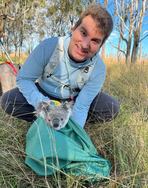
Converting a Hobby Servomotor to a DC Gearhead Motor1

Ted Pavlic

Dec 15, 2004 2


Summary

While there are many resources that provide instruction for modifying a hobby servomotor for continuous rotation, few resources give instruction on how to convert a hobby servomotor to a simple DC gearhead motor. Because hobby servomotors are packaged with compact gear trains and robust DC motors, the synthesis of a DC gearhead motor from a hobby servomotor provides for a convenient locomotion actuator package for small robotics applications. This package is ideal for robotics controllers that lack a large number of digital outputs for servomotor control but do have a number of simple programmable pulsed DC or analog outputs that have strong power support for driving DC motors. This document outlines this conversion from simple hobby servomotor to robust DC gearhead motor. The Contents page of this document can be used as a quick reference listing the necessary steps for this conversion.

Contents

1  Introduction and Background
    1.1  The Typical Continuous-Rotation Servomotor Approach
    1.2  Problems with the Typical Approach
    1.3  Servomotors as DC Gearhead Motors
2  Instructions for Converting the Servomotor
    2.1  Disassemble the Servomotor into Components
        2.1.1  Open the Servomotor
        2.1.2  Carefully Remove the Gear Train
        2.1.3  If Possible, Remove Motor-Circuitry Combination from Housing
    2.2  Remove Unneeded Servomotor Electronics
        2.2.1  Separate DC Motor from Circuitry
        2.2.2  Salvage Wires from Electronics
        2.2.3  Attach the Wires Directly to the DC Motor
    2.3  Assemble the DC Gearhead Motor
        2.3.1  Reinsert the DC Motor
        2.3.2  Modify the Gear Train for Continuous Rotation
        2.3.3  Reassemble the Gear Train and Reinsert into the Housing
        2.3.4  Reassemble the Servomotor Housing
        2.3.5  Test the Motor Before Applying Power to It
3  Some Important Remarks
    3.1  Voltage Regulation to the DC Gearhead Motor
    3.2  Motor Gear Train Binding as an Electrical Wiring Problem
    3.3  Use a Capacitor Close to the Motor
    3.4  Voltage Regulation is Often Not Necessary

List of Figures

    1  Top View of Open Servomotor
    2  Open Servomotor Adjacent to Removed Gear Train
    3  Cleanly Removed Electronics Adjacent to Housing and Gear Train
    4  Large Gear with Rotation Stop Adjacent to Same Gear without Rotation Stop

1   Introduction and Background

1.1   The Typical Continuous-Rotation Servomotor Approach

Many web sites are available that instruct how to turn a simple hobby servomotor like the Futaba(R) S-1483 into a continuous-rotation servomotor.4 The resulting motor is still controlled as a servomotor. In other words, a pulse width modulated (PWM) carrier signal still is needed to communicate a desired angle to servo electronics onboard the modified servomotor. Those electronics then move the modified servomotor output shaft to the desired reference angle. However, the modifications made replace the servo electronics' output angle feedback with static feedback representing an unmoving output shaft. The mechanical stops that prevent continuous rotation of the output are also removed. Thus, if the servomotor is commanded to move to an angle other than the angle represented by the static feedback, the motor will rotate continuously in one direction or the other.

1.2   Problems with the Typical Approach

The typical continuous-rotation servomotor approach is ideal for controllers that are designed primarily for controlling servomotors. However, many controllers for small robotics applications have few digital transistor-transistor logic (TTL) outputs that can be used to generate the necessary PWM control signal for hobby servomotors. For example, the Handy Board only has two digital outputs truly available for servomotor control, and only one of them is easily accessible; however, it does have four H-bridge outputs primarily meant for directly driving simple direct current (DC) motors.5 In these cases, servomotor control outputs are scarce, and it is desirable to control locomotion actuators with more powerful analog or pulsed DC outputs. This leaves the servomotor control outputs available for lower power application specific actuators that do not necessarily need continuous rotation.

1.3   Servomotors as DC Gearhead Motors

When a controller already provides programmable outputs with sufficient power support to directly drive DC motors, it is common to combine these outputs with simple DC motors for locomotion actuation. However, in these cases the DC motors frequently require an external gear train to provide enough torque to drive the robot. The implementation of this gear train can be cumbersome and complex to integrate with the selected DC motors.
Hobby servomotors, however, are constructed with a compact nylon gear train at the output of a relatively reliable DC motor. Rather than modifying the servomotor electronics for continuous rotation, removing those electronics completely allows for control of the internal DC motor directly. This then gives the designer access to a very compact power train solution more than adequate for most small robotics applications.
Additionally, because of the robustness of the DC motors used in most hobby servomotors, the control voltage to the motor often can safely be applied at much higher than the five volts typically provided as power support for the standard application of the servomotor. Thus, modifying a servomotor to be used as a DC gearhead motor yields a convenient powerful locomotion power train component. The DC gearhead motor can be driven directly as a standard DC motor, or may have a regulated control signal to help extend the motor's longevity.

2   Instructions for Converting the Servomotor

2.1   Disassemble the Servomotor into Components

2.1.1   Open the Servomotor

First, remove any output attachment connected to the servomotor so that the only the teeth of the output shaft are exposed.
Then, open the servomotor housing by removing the four long screws accessible from the bottom of the unit.
After removing the four screws, it should be easy to remove the small pieces that cover the top and the bottom of the unit, thus exposing the motor and circuitry from the bottom and the nylon gear train from the top. See Figure 1.
Figure 1: Top View of Open Servomotor

2.1.2   Carefully Remove the Gear Train

Carefully remove each gear in the gear train. Note that the nylon gears may be lubricated, and thus care should be taken when handling the gears. This gear train will eventually have to be reassembled, so be sure to remember the original configuration. It may be helpful to reassemble the gear train away from the servomotor to keep each gear in its correct configuration.
Now that gear train is completely removed, the actual output shaft of the DC motor as well as the notched potentiometer shaft should be exposed. See Figure 2.
Figure 2: Open Servomotor Adjacent to Removed Gear Train

2.1.3   If Possible, Remove Motor-Circuitry Combination from Housing

The eventual goal of the following steps is to remove the circuitry that is attached to the DC motor. It is easiest to accomplish this by first removing the motor and circuitry completely from the housing, but it is not necessary to do so.
If unable to remove the motor and circuitry completely, read the following steps up through reassembling the motor and improvise a method of achieving the same result. This process need not be delicate as only the motor, housing, and gear train need to survive it.
There are two common configurations that have relatively easy methods for removing the motor-circuitry combination:
Motor Fastened with Screws    Often, the motor is held in place by screws accessible from the top of the unit after the gear train has been removed. If these screws are now visible, remove them. Apply pressure to the DC motor output shaft and the potentiometer input shaft in order to remove the DC motor and servomotor electronics from the housing. See .
Motor Held with Small Tabs    If no screws are accessible at the top of the unit under the gear train, the motor and circuitry are often held in place simply by small tabs, and thus with enough force can be popped out of the unit. Apply pressure to the DC motor output shaft and the potentiometer input shaft to dislodge the DC motor and servomotor electronics from the housing.
In either case, a lot of pressure may need to be applied to the output motor shaft and the potentiometer input shaft in order to "pop" the motor and circuitry out from the bottom of the open housing. Because the circuitry is entirely unneeded for the DC gearhead motor, it is acceptable for the circuitry to crack during this application of pressure. Figure 3 shows clearly removed servomotor electronics adjacent to the open servomotor housing.
Figure 3: Cleanly Removed Electronics Adjacent to Housing and Gear Train
Impossible to Remove Motor-Circuitry Combination    If it is not possible to remove the motor and circuitry combination, it may be helpful to push hard enough on the potentiometer as to dislodge the circuitry to which its connected from the housing. This will allow the circuitry to be removed from the housing once its connection to the DC motor is severed.

2.2   Remove Unneeded Servomotor Electronics

2.2.1   Separate DC Motor from Circuitry

At this point, it is necessary to remove the DC motor from the servomotor circuitry. There are two very similar ways to doing this. Both are equally valid, but one may be easier to accomplish than the other, especially if the motor-circuitry combination was not removed completely from the housing. Regardless of the method, care should be taken to prevent the long wires going into the servomotor that connect to the electronics from being damaged.
Physically Cut Circuitry Away    The simplest method of separating the servomotor electronics and the DC motor is to clip the circuitry in half so that the only circuitry still connected to the motor resides completely underneath the motor. This is easy to do with a small pair of diagonal cutters.
Desolder DC Motor from Servomotor Electronics    The cleanest method of separating the servomotor electrons and the DC motor is to apply a soldering iron on the DC motor leads, and as the solder melts, pull the circuit board away. Often, this requires a two person team to complete.
Note that these two methods may be combined. The circuitry can be cut away and then the remaining circuitry can be removed with a soldering iron.

2.2.2   Salvage Wires from Electronics

The control electronics previously removed should have three wires connected to it. It is most convenient to use these wires to direct the power into the resulting DC gearhead motor. While cutting these wires from the circuit board and stripping them is simple to do, it is not difficult to apply a soldering iron to the circuit board location where they are connected and pull them off of the board as the solder melts.
Since only two wires are needed for the DC gearhead motor, it may be useful to remove one of the two wires. This choice is arbitrary, but depending on how the DC gearhead motor interacts with the motor electronics that will control it, it may make the most sense to remove the middle wire.

2.2.3   Attach the Wires Directly to the DC Motor

Now solder the two remaining wires to the two leads coming from the bottom of the motor. If a portion of the circuit board is still attached to the motor, these leads will be protruding through the bottom of that circuit board. To each lead coming from the motor, solder one wire.
Note that these wires will most likely be braided. Be careful not to allow any of the braid from one wire to touch any of the braid from the other wire. If the leads of the motor are shorted together, during operation this can damage the controller driving the motor. Additionally, if the motor leads are shorted together, a sufficient amount of back-EMF will not build up, and the gear train will appear to bind up, even though this is an electrical problem and not a mechanical problem. Often this electrical wiring problem is misdiagnosed as a mechanical problem with the gear train.

2.3   Assemble the DC Gearhead Motor

2.3.1   Reinsert the DC Motor

Insert the DC motor that now lacks servomotor control circuitry back into the servomotor housing. At this point, the DC motor's output shaft should protrude out the top of the servomotor housing. Fasten the DC motor as necessary by either "snapping" it in place, screwing it place, or doing whatever is necessary to reverse the previous process of removing it.

2.3.2   Modify the Gear Train for Continuous Rotation

Before reassembling the gears into the gear train, a small plastic "stop" needs to be removed from the output shaft gear. This "stop", which is perpendicular to the face of this largest gear, prevents the gear train output from rotating continuously. It can be clipped off of the gear with some sort of cutters or knife. The resulting gear surface will need to be smooth to allow for easy continuous rotation. Use a knife, sand paper, a rotary tool, or something similar in order to make sure the gear face is sufficiently smooth. Figure 4 shows this large gear before and after the proper modification.
Figure 4: Large Gear with Rotation Stop Adjacent to Same Gear without Rotation Stop

2.3.3   Reassemble the Gear Train and Reinsert into the Housing

Reassemble the gears and place them back into the housing on top of the DC motor. Take care to reassemble them properly so that DC motor rotations translate to output shaft rotations. Also take care to keep as much lubrication remaining on the gears as possible. n.

2.3.4   Reassemble the Servomotor Housing

Put the top and bottom pieces back on the housing and attach them with the four long screws. What remains is now a completed DC gearhead motor .

2.3.5   Test the Motor Before Applying Power to It

Try turning the output of the gear train. In order to do this, it may be necessary to attach one of the servomotor wheel attachments. The gear train output should be able to continuously rotate past 360 degrees with uniform resistance due to the DC motor's internal resistance. The three common problems are as follows:
Gear Train Binding    If the gear train seems to bind up, make sure that the DC motor leads are not being shorted, and make sure the gear train is correctly assembled.
No Resistance to Rotation    If the output turns with almost no resistance and no sound, make sure the gear train is assembled correctly; more specifically, make sure that all of the gears are interfacing with each other.
Nonuniform Resistance to Rotation    If there is a spot of resistance in the rotation that seems greater than the resistance in the rest of the rotation, make sure that the "stop" has been removed completely.

3   Some Important Remarks

3.1   Voltage Regulation to the DC Gearhead Motor

It may be desirable to add voltage regulation in line with the two wires going to the DC gearhead motor. Most hobby servomotors are designed expecting that a maximum of five volts will be applied to the DC motor, so it makes sense to regulate the output to the DC gearhead motor so that it reaches no more than five volts. This can be done with linear regulation, non-linear clipping, or a number of other methods. Seek documentation on the construction of such regulation circuitry elsewhere. Choose the appropriate regulation keeping in mind the motor controller and application.

3.2   Motor Gear Train Binding as an Electrical Wiring Problem

When soldering the wires onto the motor within the housing, be careful not to let them wires touch. Because those wires are most likely braided, it is very easy for some strands of the braid to reach over and short against the other motor lead or a strand from the other wire.
Not only can this condition damage the motor controller connected to the DC gearhead motor, but this electrical short will prevent the DC motor from building up any back-EMF, and the motor will have an urge to stall. Because of the gear ratio on the output of that motor, this stalling urge will be very apparent, even when the DC gearhead motor is disconnected from its controller and is being backdriven manually.
After you assemble the DC gearhead motor, try to turn the output manually. If any binding occurs and the gear train appears to be correctly assembled, then most likely the wires soldered to the motor leads are shorting inside the housing. Even though this will appear to be a mechanical problem, its roots are electrical, and the wiring needs to be reviewed.

3.3   Use a Capacitor Close to the Motor

A large capacitor can be added as close to the motor as possible with as short of leads as possible in order to help protect the motor controller and smooth the operation of the DC gearhead motor. It is highly advisable to add this capacitor, though with well-behaved motors, it may not be necessary.
Note that this capacitor can be very large, but if after the application of the capacitor the motor is sluggish to respond to changes in its input, the size of the capacitor should be reduced. Increasing it any further will only degrade motor response and require too much turn-on current from the motor controller.

3.4   Voltage Regulation is Often Not Necessary

Most hobby servomotors are robust enough to be able to handle a maximum nine to eleven volts at input to the modified DC gearhead motor. However, it is often simple to build modular voltage regulation that interfaces to the motor controller just as the motor would and interfaces to the motor just like the motor controller would. It may be useful to keep voltage regulators built and on-hand as a safe guard and connect to the DC gearhead motor directly as necessary.
Note that the dynamics of the DC gearhead motor will greatly change with a change of input voltage. Other changes to the system may be necessary when moving from one voltage regulation scheme to another.

Footnotes:

1Figures taken from http://www.seattlerobotics.org/guide/servohack.html, December 14, 2004.
2See http://www.tedpavlic.com/general_posts.php for updates to this document.
3"Futaba(R) Servos", http://www.futaba-rc.com/servos/futm0029.html, December 15, 2004.
4"Hacking a Servo", http://www.seattlerobotics.org/guide/servohack.html, December 14, 2004.
5"The Handy Board", http://handyboard.com/, December 14, 2004.


File translated from TEX by TTH, version 3.64.
On 15 Dec 2004, 19:01.